The electronics board PCBBasic2.0
Anthony HathawayFor the last couple of months we have gotten back to circuit boards and looking at completing the project we started a long time ago. Making the shower smart and easily controllable like one would expect from modern consumer products. There’s been a lot to learn considering all we could do a few years ago was wire up a light bulb, and even then we would need to check what the difference was with the brown wire (live/positive) and the blue wire (ground/neutral).
To keep it simple last year we started working on a fully analog version of the system, just like the one below.
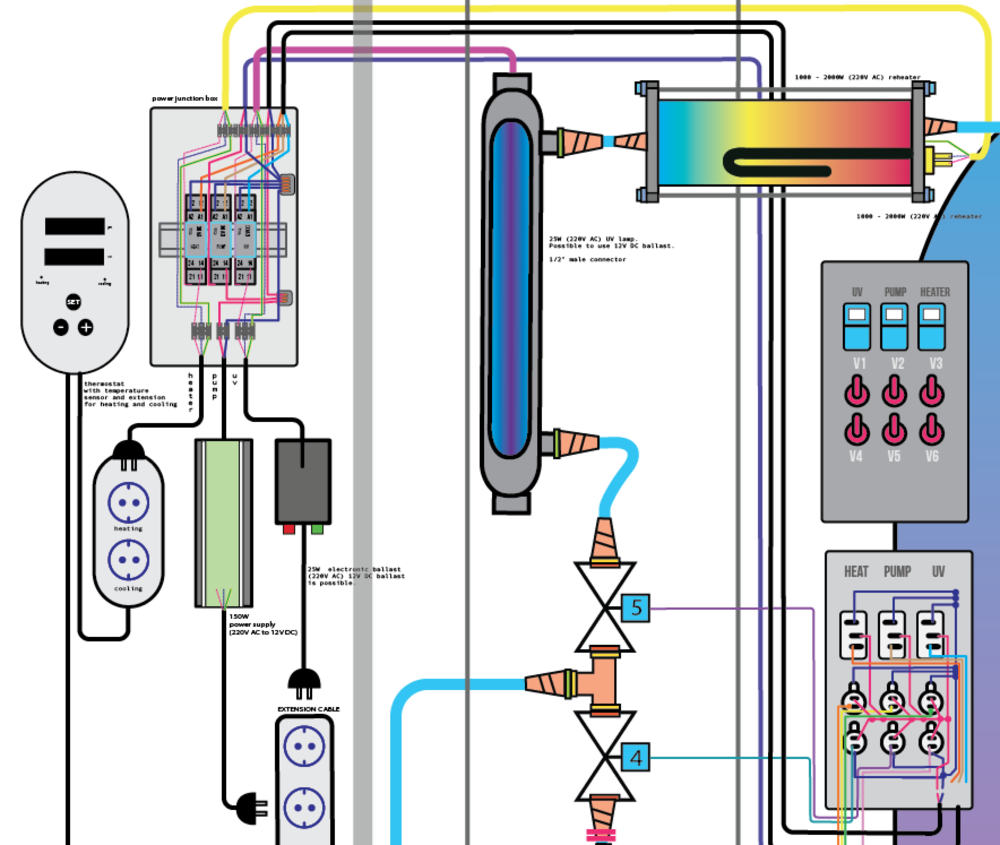
Basically it’s a switch panel and buttons where the top 3 water proof/resistant rocker switches are to activate the pump, uv and heater and a 6 toggle switch switch-board below to control the individual valves. The top 3 buttons go to the power box that activated the relays with a 1 V DC current to close the circuit for the 220V AC to power the aforementioned devices. The valves are controlled directly via the 12V DC power supply.
Anyway, that was the old one. Since then we’ve added all kindsa stuff. An integrated GFCI, fuses, an 8-channel relay module, voltage meter for the pump and a motor controller, Power button and the appropriate cable glands to keep everything up to spec. The cables should be around 18 AWG or lower (thicker).
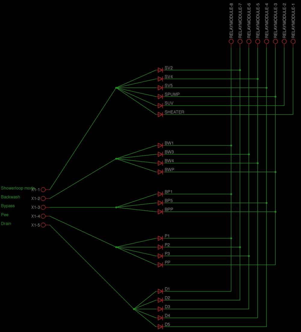
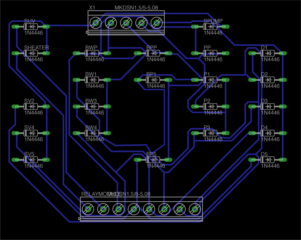
Additionally to make it easier to use in everyday use we made an analog controller. This should be done with an integrated circuit but I don’t have experience with that and the last two people I’ve tried to work with have failed to help me so I’m starting from the most basic setup that I can understand and make myself. So below you can see the schematic connecting one switch to multiple devices using diodes to keep the flow in one direction.